
Time Delay Relay Circuit Using 555 Timer IC Electronics 58 OFF Circuit Diagram Learn how to build your own time-delay relay circuit with this easy-to-follow DIY tutorial. We'll guide you through the entire process, from selecting the ri
we are going to show you how to make a Time delay relay circuit using a 555 timer IC. This circuit is able to trigger the relay from a few seconds to a few m

555 Based Adjustable Auto On Off Delay Timer Circuit Circuit Diagram
Time Delay Relay Circuit Diagram. In this circuit, if you want to use the 5V DC supply, then use the 5-volt relay instead of the 12-volt relay. The delay time depends on the R2 resistor and C1 capacitor. For the constant delay time use a fixed resistor in R2, but for the adjustable off delay time, you can use a 1M POT. I will discuss how this
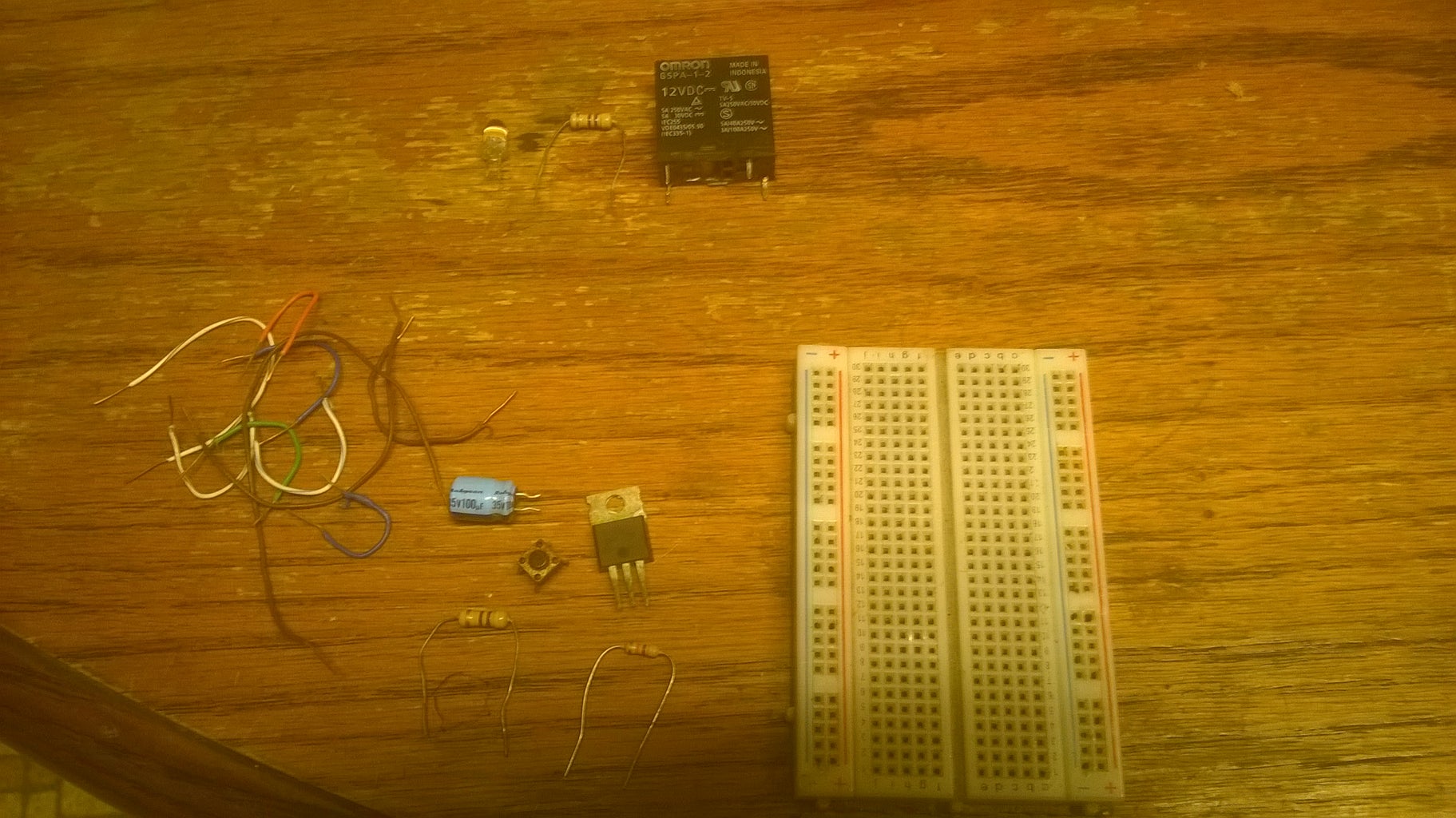
A time delay relay is a relay that stays on for a certain amount of time once activated. This time delay relay is made up of a simple adjustable timer circuit which controls the actual relay. The time is adjustable from 0 to about 20 seconds with the parts specified. The current capacity of the circuit is only limited by what kind of relay you decide to use.
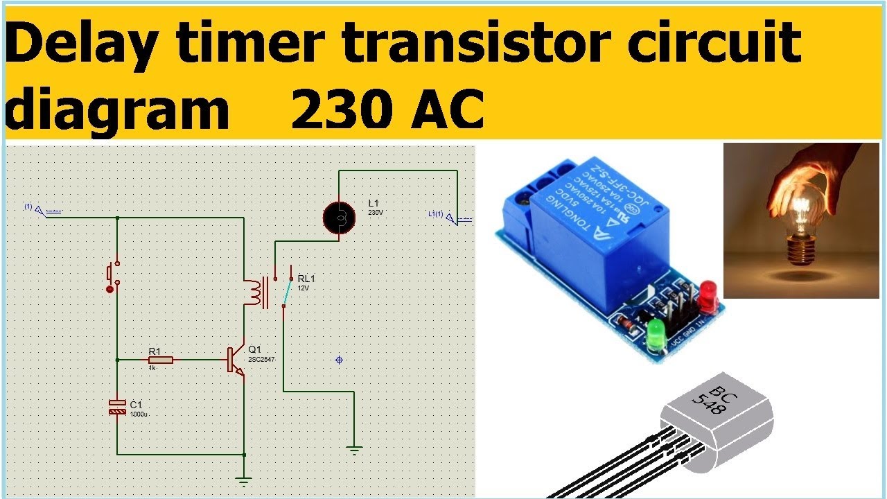
Time Delay Relay Circuit Circuit Diagram
The switch circuit consist of the transistor and the relay coupled to a diode. Once the charge from the capacitor is still preserved with time,when the push button is released,the transistor is switch on as a result of the electric field,and as such, the transistor the transistor activates the relay,which is used to drive any electric load
